
In real-time clock (RTC) and low-power timing applications, the 32.768kHz crystal oscillator is the core component determining system timekeeping accuracy and long-term reliability. What parameters and details in the datasheet of VMK3-9002-32K7680000, a miniature SMD 32.768kHz crystal resonator, make or break a design? This article will dissect its key specifications item by item, revealing selection pitfalls from frequency tolerance to load capacitance, to help you make precise decisions in portable devices, IoT terminals, and industrial timing modules.
Product Positioning and Typical Application Scenarios
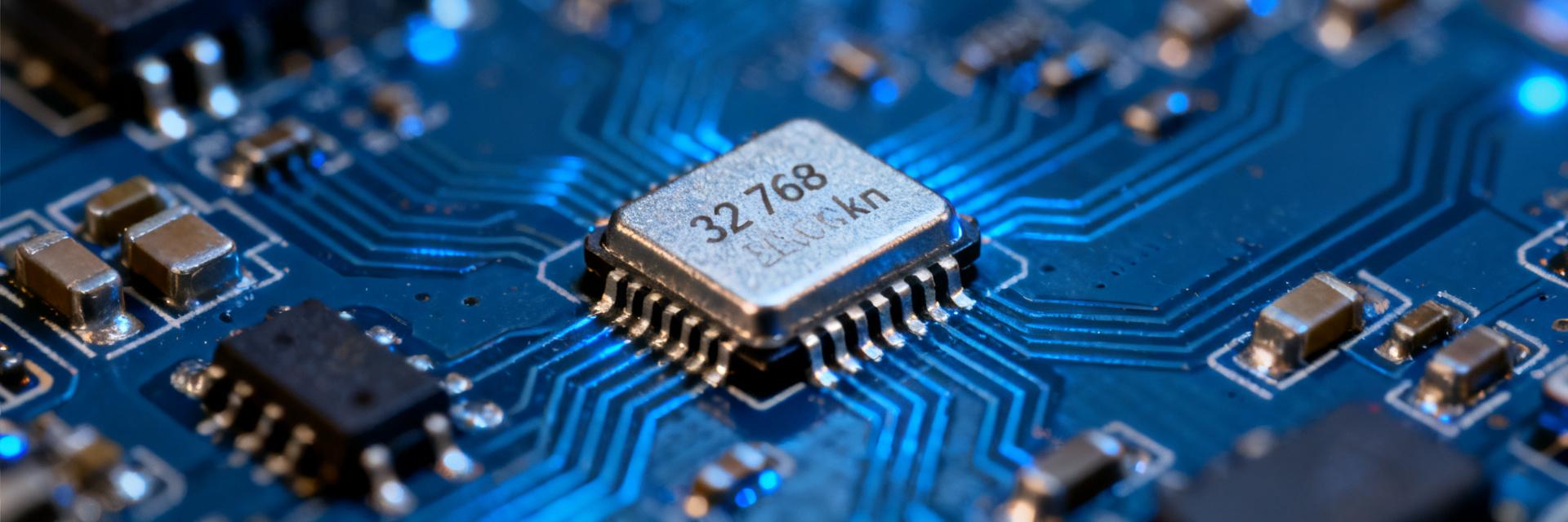
Timing Logic of the 32.768kHz Frequency
32.768kHz is 2 to the 15th power. A 1Hz second pulse can be obtained after a 15-stage binary division, making this mathematical characteristic ideal for RTC timing references. Every second of accurate timekeeping you design relies on the stable oscillation of this frequency. VMK3-9002-32K7680000 is a resonator optimized precisely for this requirement.
Target Market and Packaging Advantages of VMK3-9002-32K7680000
This model adopts a 3.2mm × 1.5mm miniature SMD package, suitable for high-density PCB layouts, and is widely used in smartwatches, wireless sensor nodes, and portable medical devices. Its small size and low power consumption give it significant advantages in space-constrained scenarios requiring long-term battery power.
Step-by-Step Breakdown of Core Electrical Parameters
Nominal Frequency and Frequency Tolerance: The Cumulative Time Error Behind ±20ppm
A nominal frequency of 32.768kHz combined with a ±20ppm frequency tolerance means a daily timekeeping error of approximately ±1.73 seconds. You need to evaluate whether this deviation is acceptable in your application. If the system requires a monthly error of less than 30 seconds, ±20ppm is a reasonable starting point; if the requirements are stricter, temperature compensation or calibration algorithms must be considered.
Matching Logic of Load Capacitance and Equivalent Series Resistance (ESR)
The typical load capacitance of VMK3-9002-32K7680000 is 12.5pF, and the maximum ESR is typically 70kΩ. Mismatched load capacitance will directly cause a frequency shift. You must configure external load capacitors on the PCB to match the datasheet while considering the impact of parasitic capacitance. An excessively high ESR can cause start-up difficulties, especially under low drive level conditions.
| Parameter | Typical Value | Design Impact |
|---|---|---|
| Nominal Frequency | 32.768kHz | Timing Reference |
| Frequency Tolerance | ±20ppm | Daily error approx. ±1.73 seconds |
| Load Capacitance | 12.5pF | Requires matching external capacitors |
| Maximum ESR | 70kΩ | Affects start-up margin |
Temperature Characteristics and Turnover Temperature: Stability Performance from -40°C to +85°C
This crystal oscillator is designed with a turnover temperature, typically around +25°C. Over the -40°C to +85°C range, the frequency varies parabolically with temperature. In wide-temperature applications, you need to calculate the actual frequency deviation at operating temperatures and introduce software temperature compensation if necessary.
Hidden Design Essentials in the Datasheet
Drive Level and Negative Resistance: Boundary Conditions to Prevent Oscillation Failure
An excessively high drive level accelerates crystal aging, while an excessively low one may lead to oscillation failure. You should ensure that the negative resistance provided by the oscillation circuit is 3 to 5 times greater than the crystal's ESR. The recommended drive level for VMK3-9002-32K7680000 is 0.1μW to 1μW, and the negative resistance must be measured during design.
Engineering Compensation Strategies for Aging Rate and Long-Term Frequency Drift
The typical aging rate is ±3ppm/year. For devices expected to run for more than five years, the cumulative drift can reach ±15ppm. You can reserve frequency fine-tuning registers in the firmware, combined with factory calibration and periodic temperature compensation, to control long-term errors within an acceptable range.
Synergistic Optimization of Parasitic Capacitance and PCB Layout
Trace parasitic capacitance adds to the load capacitance, causing the actual frequency to shift lower. You should place the crystal as close to the MCU as possible, shorten the traces, and lay a complete ground plane beneath the crystal. Load capacitors should be temperature-stable, such as C0G material.
Selection Comparison and Common Misconceptions
Horizontal Parameter Comparison with Similar 32.768kHz SMD Crystals
Compared with similar products, VMK3-9002-32K7680000 demonstrates a balanced performance in ESR and load capacitance matching. Although some competitors claim lower tolerances, their higher ESR increases the risk of oscillation failure. You should comprehensively evaluate tolerance, ESR, and load capacitance rather than focusing on a single index.
Case Study: Timekeeping Deviation Caused by Neglecting Load Capacitance Matching
An IoT terminal used a 10pF load capacitor instead of the 12.5pF required by the datasheet, resulting in an additional daily timekeeping error of approximately 2.5 seconds. This case demonstrates that neglecting load capacitance matching directly amplifies timekeeping deviations. You must measure the frequency and adjust the capacitors during the prototyping stage.
Practical Design Checklist
From Datasheet to Schematic: Key Parameter Verification Flow
You should establish a checklist: verify nominal frequency, load capacitance, ESR, drive level, and operating temperature range. Note the datasheet parameters in the schematic to ensure the oscillation circuit design aligns with the datasheet.
Recommendations for Testing Verification and Mass Production Consistency Control
During the prototyping stage, measure the start-up time, frequency deviation, and negative resistance. During mass production, it is recommended to sample-test the frequency tolerance and ESR, and monitor batch consistency of the load capacitance. You should reserve frequency fine-tuning margin to cope with batch drift. For mass production consistency control, individual units should be calibrated during the factory calibration stage to offset temperature drift and aging drift generated during long-term operation.
Key Summary
- The ±20ppm tolerance of VMK3-9002-32K7680000 corresponds to a daily error of approximately ±1.73 seconds; evaluate your application's tolerance.
- A 12.5pF load capacitance and 70kΩ maximum ESR are the core of matching design; mismatch directly leads to timekeeping deviations.
- The temperature characteristic is parabolic; calculate the actual deviation and consider compensation within the -40°C to +85°C range.
- The negative resistance should be 3 to 5 times greater than the ESR, with the drive level controlled between 0.1μW and 1μW.
- An aging rate of ±3ppm/year requires reserved frequency fine-tuning and temperature compensation strategies for long-term operation.
FAQ
Can the load capacitance of VMK3-9002-32K7680000 be replaced arbitrarily?
No. The load capacitance directly determines the oscillation frequency, and replacing it with a different value will cause a frequency shift. You should strictly configure the external capacitors according to the 12.5pF required by the datasheet, taking PCB parasitic capacitance into account, and adjust through actual measurement if necessary.
How to determine if VMK3-9002-32K7680000 starts up reliably?
You should measure the negative resistance of the oscillation circuit to ensure it is 3 to 5 times greater than the crystal's ESR. Meanwhile, observe the start-up time, which is typically within a few hundred milliseconds. If start-up is slow or fails, check the match between drive level and load capacitance.
Does this crystal oscillator require extra compensation in wide-temperature environments?
If the application requires a monthly error of less than 30 seconds, software temperature compensation is recommended within the -40°C to +85°C range. You can build a temperature-frequency lookup table in the firmware and correct the timekeeping based on actual measurement data.
What does the maximum ESR value in the VMK3-9002-32K7680000 datasheet mean?
The maximum ESR of 70kΩ represents the minimum gain condition required for oscillation start-up. The oscillation circuit you design must provide sufficient negative resistance; otherwise, it may fail to oscillate at low temperatures or low voltages. The higher the ESR, the smaller the start-up margin.