
When selecting components for embedded systems, seemingly minor details in the datasheet often determine the system's actual performance. The PIC24FJ128GA310T-I, a popular choice for 16-bit low-power applications, hides five core parameters in its datasheet that directly impact performance. Understanding these is essential for making accurate decisions during component selection and design.
Parameter One: Memory Architecture — The True Capacity of 128KB Flash and 16KB RAM
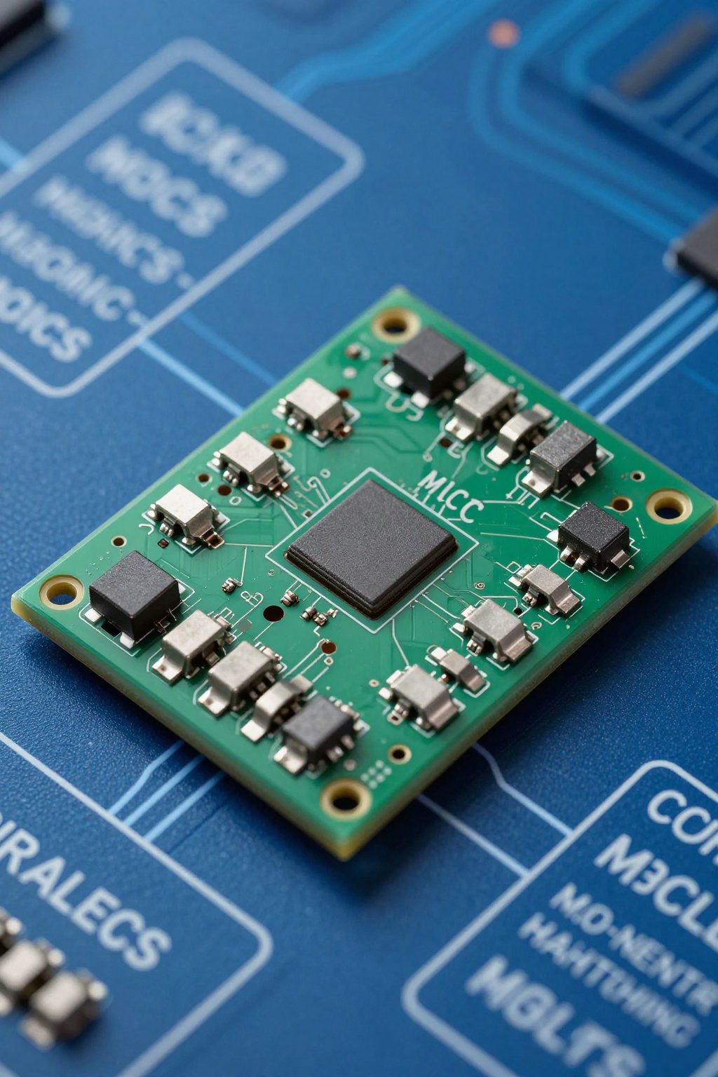
Pay attention to the difference between "nominal capacity" and "usable capacity." After accounting for configuration words, the bootloader area, and the interrupt vector table, approximately 120KB of the 128KB Flash remains available for application code. As for the 16KB RAM, it typically supports around 8 to 12 medium-complexity tasks when allocated for RTOS task stacks and communication buffers.
Storage access speed is equally critical. Flash wait states increase with higher clock frequencies; at 32 MHz, wait states are typically required, whereas RAM offers single-cycle direct access. This means that in high-frequency control loops, key variables should be prioritized in RAM to reduce the impact of fetch latency on interrupt response time.
Parameter Two: CPU Core and Instruction Execution Efficiency — Performance Limits of the Enhanced 16-bit Architecture
This device features an enhanced 16-bit CPU, with most instructions executing in a single cycle. Combined with a performance benchmark of approximately 1.5 DMIPS/MHz, it ranks mid-to-high among comparable 16-bit MCUs. You should carefully consult the "Instruction Execution Timing Table" in the datasheet to optimize hot-spot code and avoid wasting real-time budget on multi-cycle instructions.
The interrupt response mechanism is the bottom line for hard real-time tasks. The manual specifies interrupt latency and nested priority rules, ensuring deterministic CPU response in multi-source interrupt scenarios. This is especially important for time-sensitive applications such as motor control and sensor acquisition; you should plan priority allocation early in the design phase.
| Performance Metrics | Value/Description | Engineering Significance |
|---|---|---|
| Flash Capacity | 128KB (nominal) | Approximately 120KB actually available; configuration space must be reserved |
| RAM Capacity | 16KB | Supports 8–12 medium-complexity RTOS tasks |
| CPU Performance | ~1.5 DMIPS/MHz | Primarily single-cycle instructions, suitable for real-time control |
| Interrupt Latency | Deterministic | Ensures precision in responding to hard real-time tasks |
Key Summary
- The PIC24FJ128GA310T-I has approximately 120KB of usable flash out of its 128KB capacity, and its 16KB RAM can support the allocation of medium-complexity RTOS tasks.
- The enhanced 16-bit CPU features a high proportion of single-cycle instructions, delivering approximately 1.5 DMIPS/MHz; code optimization should be guided by the instruction execution timing table.
- Interrupt latency and nested priority rules are clearly defined, ensuring deterministic responses for hard real-time tasks such as motor control and sensor acquisition.
- The core value of the datasheet lies in understanding the interdependencies among memory, core performance, power consumption, peripherals, and electrical parameters.
Frequently Asked Questions
In the PIC24FJ128GA310T-I datasheet, how should storage capacity be accurately estimated?
Do not rely solely on nominal values. You must account for configuration words, the bootloader area, and the interrupt vector table overhead; thus, about 120 KB of the 128 KB Flash is actually usable. For RAM, reserve headroom for RTOS task stacks and communication buffers, and it is recommended to allocate application data space at 70% of 16 KB.
What impact does this model's interrupt response latency have on real-time control?
The datasheet provides deterministic interrupt latency and nested priority rules. In multi-source interrupt scenarios, CPU response is predictable, making it suitable for motor control and sensor acquisition. You should assign priorities in advance to ensure high-priority tasks receive the shortest response path.
How can you use the datasheet to evaluate the instruction execution efficiency of the PIC24FJ128GA310T-I?
Consult the "Instruction Execution Timing Table" to identify multi-cycle instructions and optimize hot code. By referencing approximately 1.5 DMIPS/MHz, you can make horizontal comparisons with similar 16-bit MCUs to determine whether it meets the real-time budget for high-frequency control loops.
What memory access issues should be noted when operating the PIC24FJ128GA310T-I at high frequencies?
Flash wait states increase as the clock frequency rises; at 32 MHz, wait states are typically required, whereas RAM offers single-cycle direct access. This means that in high-frequency control loops, critical variables should be prioritized for placement in RAM to minimize the impact of instruction-fetch latency on interrupt response time.