
According to industry statistics, approximately 30% of electronic component selection errors stem from misreading or overlooking key parameters in the datasheet.RM06F9530CTAs a precision surface-mount resistor, its datasheet contains numerous core pieces of information that determine circuit performance—ranging from the tolerance limits of the nominal resistance value of 953Ω, to the power derating curve at 70°C, and even the resistance drift characteristics under long-term load. This article will break down each layer.RM06F9530CTof the datasheet, helping you accurately understand parameter meanings, characteristic boundaries, and typical application scenarios, thus avoiding selection pitfalls.
Analysis of RM06F9530CT Product Positioning and Naming Conventions
Decoding the Model Number: The Full Meaning from "RM06" to "9530CT"
You have receivedRM06F9530CTWhen dealing with this model, the first step is to understand its coding logic. "RM" stands for the precision chip resistor series; "06" corresponds to the imperial 0603 package size; and "9530" is the resistance value code—where the first three digits, "953," represent the significant figures, and the final digit, "0," indicates multiplication by 10⁰, resulting in 953 Ω. "C" denotes a tolerance of ±1%, while "T" indicates tape-and-reel packaging. By grasping this coding scheme, you can quickly locate key parameters when consulting any datasheet, rather than sifting through them one by one.
Overview of Package Size and Physical Structure
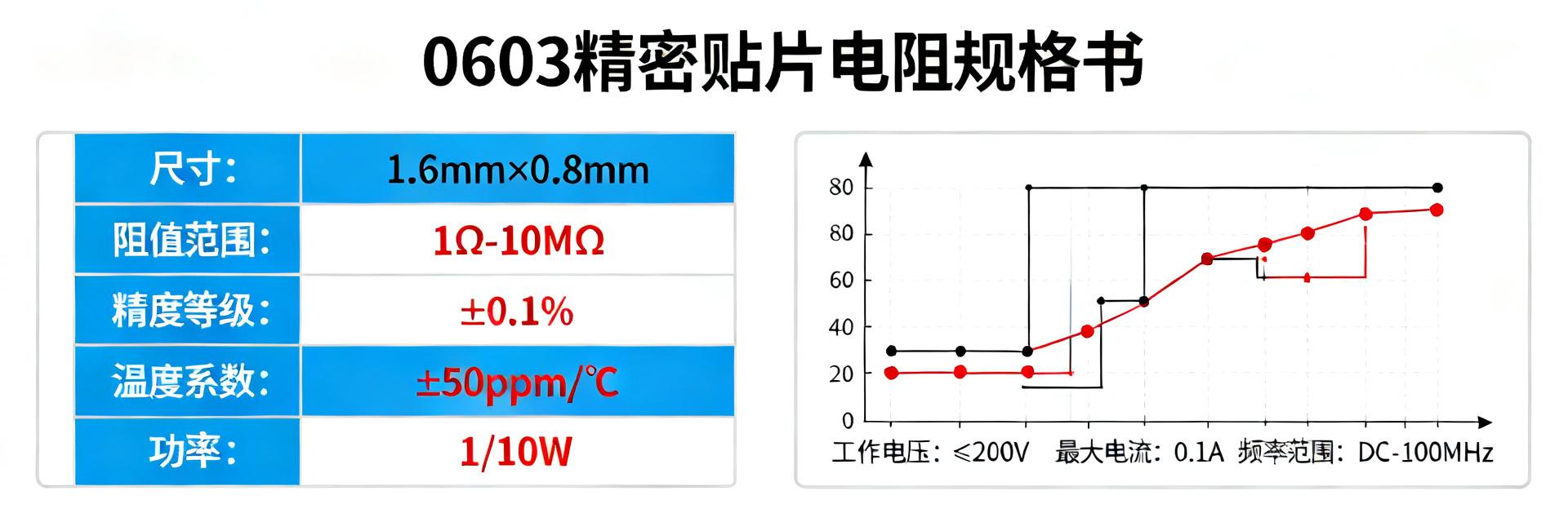
The 0603 package corresponds to the metric size of 1.6mm × 0.8mm, with a three-layer electrode structure on the solder terminals (inner electrode/barrier layer/weldable layer), and a high-purity alumina ceramic substrate. Compared to 0402, 0603 achieves a better balance between mounting density and heat dissipation; compared to 0805, it saves more PCB area but has lower power-handling capability. Choose 0603 for high-density layouts, and consider larger packages when higher power margin is required.
Detailed Reading of Core Electrical Parameters
| Parameter Item | Specification Value | Engineering Significance |
|---|---|---|
| Nominal Resistance Value | 953 Ω | Standard value from the E96 series, suitable for precision voltage division |
| Tolerance Accuracy | ±1% | Maximum deviation range at room temperature: 943.5Ω ~ 962.5Ω |
| Temperature Coefficient (TCR) | ±100 ppm/℃ | For every 1°C change, the resistance drifts by approximately 0.095Ω |
| Rated Power | 1/10 W (0.1 W) | Above 70°C, strict derating is required |
| Maximum Operating Voltage | 50 V | To prevent high-voltage breakdown or arc discharge |
| Operating Temperature Range | -55℃ ~ +155℃ | Covers industrial-grade and some automotive-grade applications |
Resistance Value and Accuracy: The practical significance of 953Ω ±1%
953Ω comes from the E96 series (a standard resistor value table with 1% tolerance), and is not an arbitrarily chosen value. A ±1% tolerance means the actual resistance falls between 943.5Ω and 962.5Ω. In voltage divider or feedback circuits, this deviation directly translates into output voltage error. More importantly, you must also account for the temperature coefficient of resistance (TCR)—the datasheet specifies a typical value of ±100 ppm/°C, which results in a resistance variation of up to ±2.1% across the full temperature range of -55°C to +155°C, far exceeding the tolerance itself. When evaluating total error, both tolerance and TCR must be combined in the calculation.
Power and Voltage: Rated Power, Maximum Operating Voltage, and Derating Curves
The 0603 package typically has a rated power of 1/10 W (0.1 W), corresponding to a maximum operating voltage of approximately 50 V. The derating curve in the datasheet is critical: the device can operate at full load below 70°C, but above 70°C, the power rating is linearly derated until it reaches zero at 155°C. When using the component in high-temperature environments or enclosed spaces, you must recalculate the actual allowable power according to the derating curve. For pulsed-load applications, you should also refer to the pulse-power withstand curve, as the design margin for continuous loads and pulsed loads follows entirely different logic.
Temperature Characteristics and Operating Environment Limits
The operating temperature range of -55°C to +155°C covers the vast majority of industrial and automotive applications. A TCR of ±100 ppm/°C requires particular attention in precision measurement and reference circuits—each 10°C change results in a resistance drift of approximately 0.95 Ω for a 953 Ω resistor. In high-humidity environments, the long-term stability of chip resistors is also affected by moisture ingress; it is recommended to apply conformal coating to the PCB to enhance protection. When selecting components for outdoor or high-humidity applications, this factor should be factored into your reliability budget.
Key Summary
- RM06F9530CTA 0603 package, 953 Ω ±1% precision chip resistor, with standard E96 series values, suitable for voltage division and feedback circuits.
- Rated power: 1/10 W; above 70°C, derating according to the derating curve is required, and in high-temperature environments, be sure to recalculate the power margin.
- The typical TCR value is ±100 ppm/°C, and the total error over the entire temperature range must be assessed by combining tolerance and temperature drift.
- Operating temperature: -55°C to +155°C. In high-humidity environments, it is recommended to apply a protective coating to ensure long-term stability.
Frequently Asked Questions
RM06F9530CTIn which circuits is the 953Ω resistance most commonly used?
The 953Ω resistor is often found in power supply feedback voltage divider networks and operational amplifier gain-setting circuits. With its ±1% accuracy and low TCR, it can meet the requirements of most precision voltage division applications. When designing a feedback network, you should calculate the required resistance based on the reference voltage and the desired voltage division ratio to confirm whether 953Ω is suitable for your target output.
How to determine from the datasheetRM06F9530CTwhether it is suitable for high-temperature applications?
Refer to the derating curve: below 70°C, full load is 0.1W; above that, power decreases linearly. Your actual power consumption at the maximum operating temperature must be lower than the derated allowable value. If the ambient temperature approaches 155°C, the device's power handling capability will approach zero, requiring you to switch to a larger package or a higher-power-rated product.
RM06F9530CTHow do the ±1% accuracy and ±100ppm/°C TCR together affect circuit error?
Tolerance refers to the initial deviation at room temperature, while TCR represents additional drift caused by temperature changes. When evaluating across the entire temperature range, the total error is approximately ±1% plus ±100ppm/°C × ΔT. For example, if ΔT = 100°C, the temperature-induced drift contributes about ±1%, bringing the total error to around ±2%. You should accordingly verify your circuit's accuracy budget.
RM06F9530CTHow is reliability in high-humidity environments ensured?
The long-term stability of chip resistors is affected by moisture ingress. It is recommended to apply conformal coating to the PCB to enhance protection, or to factor humidity into the reliability budget when selecting components for outdoor or high-humidity environments; if necessary, choose packaging technologies that offer superior moisture resistance.